Grinding power model for flute grinding of solid tools based on equivalent chip thickness
-
摘要: 磨削功率与整体刀具容屑槽的磨削质量密切相关。提出一种基于当量磨削层厚度的整体刀具容屑槽磨削功率模型,将砂轮离散化为一组等厚度的砂轮薄片,由砂轮与刀具间的瞬时接触线计算各砂轮薄片的接触弧长;再通过引入磨削接触区形状系数计算沿砂轮宽度方向逐渐变化的当量磨削深度和当量进给速度,得到各砂轮薄片对应的当量磨削层厚度;在此基础上建立容屑槽磨削功率模型,并通过磨削实验对模型进行验证。结果表明:模型的功率预测值与测量值间的最大相对误差 < 15.0%;沿砂轮宽度方向的最大当量磨削层厚度和最大单位宽度磨削功率存在于砂轮边缘处,将导致砂轮宽度方向上的非均匀磨损。Abstract:
Objectives During the flute grinding process of solid tools, the majority of grinding power is converted into grinding heat. Excessive grinding power can cause a rapid temperature rise on the surface of the contact area between the grinding wheel and the tool, which can easily lead to grinding burns and eventually tool failure. A grinding power model for flute grinding of solid tools is proposed based on equivalent chip thickness, aiming to achieve precise prediction and control of grinding power for flute grinding. Methods A kinematic model for flute grinding is established using homogeneous coordinate transformation. On this basis, according to the theory of conjugate surfaces, the instantaneous contact line between the grinding wheel surface and the flute surface during the grinding process is obtained, and the grinding wheel is discretized into a set of equally thick grinding wheel slices. The grinding contact arc length is obtained by calculating the intersection points between the grinding wheel slices and the tool cylindrical surface. Flute grinding is regarded as external cylindrical grinding with a special contact zone shape. By introducing the contact-area-shape coefficient to define the equivalent grinding depth and the equivalent feed rate of each grinding wheel slice, the formula for calculating the equivalent grinding layer thickness of flute grinding is derived. When the linear speed of the grinding wheel, the axial feed speed of the workpiece, and the grinding contact arc length of each grinding wheel slice are known, the equivalent chip thickness of each grinding wheel slice can be calculated as long as the shape coefficient of the contact area is given. The cross-section profiles of the chute are discretized into small triangles, and the area of the cross-section profile of the chute is obtained by calculating the area of each triangle. The material removal rate of the chute during grinding is determined by combining the axial feed velocity of the workpiece. According to the principle of conservation of material removal rate, the formula for the shape coefficient of the contact area is derived. Based on the mathematical relationship between the local grinding power of each grinding wheel slice and the thickness of the equivalent grinding layer, the empirical model for flute grinding power is established. The experimental verification of the model is carried out on an ANCA MX7 CNC tool grinding machine. The flute with a spiral angle of 30° is ground on a cemented carbide rod with a metal-bonded diamond wheel. The spindle power data of the machine tool PLC is recorded using the data recording function of iGrind grinding software. The spindle power includes grinding power and spindle idle power, so grinding power is obtained by subtracting idle power from spindle power. Twenty sets of grinding experiments are carried out under different grinding parameters, and an overdetermined equation set is established by substituting the grinding power data of four sets of experiments into the power model. By solving this equation system, the two empirical constants in the model are obtained. Then, the grinding power model is used to predict the grinding powers of twenty sets of grinding experiments, and the predicted grinding powers are compared with the actual grinding powers. Results The comparison results show that the predicted grinding powers are close to the actual grinding powers, and the maximum relative error of the predicted grinding power is less than 15%. The equivalent chip thickness of each wheel slice and the grinding power per unit width vary gradually along the width of the grinding wheel, and the maximum equivalent chip thickness and the maximum grinding power per unit width exist at the edge of the grinding wheel. Conclusions The proposed grinding power model based on equivalent chip thickness can precisely predict the grinding power during the flute grinding process of solid tools, and obtain the distribution of grinding power in the width direction of the grinding wheel. The grinding power can be precisely controlled by adjusting grinding parameters with this model, and the maximum equivalent chip thickness and the maximum grinding power per unit width exist at the edge of the grinding wheel during the grinding process of the chute, which will lead to non-uniform wear in the direction of the width of the grinding wheel. -
Key words:
- solid tool /
- flute /
- grinding power /
- equivalent chip thickness /
- helical groove
-
整体刀具的容屑槽在切削加工中主导切屑的形成与排出,其磨削质量直接影响刀具的切削性能[1]。由于材料去除量大,为了提高效率,容屑槽一般采用深切缓进给磨削的方式进行加工[1]。这种磨削方式会消耗较大的磨削功率,并在砂轮与刀具接触区产生大量的磨削热,导致刀具表面温度快速升高,容易在刀具表面产生磨削烧伤[2],导致刀具报废。因此,为了保证刀具容屑槽的磨削质量,必须对容屑槽磨削过程中的磨削功率或磨削力进行控制。
目前,关于磨削力及磨削功率的研究已经取得了大量的成果,但主要针对的是平面磨削和外圆磨削[3],而针对容屑槽磨削的研究相对较少。相比于平面和外圆磨削,容屑槽磨削过程中刀具相对砂轮做螺旋进给运动,砂轮与刀具间的接触区形状复杂,磨削力沿砂轮宽度方向变化较大且难以直接测量,这给磨削力及磨削功率的分析和建模带来一定困难[4]。赵延军等[5]采用不同刚性的砂轮磨削刀具容屑槽,分析了砂轮刚性对磨削功率、磨削区温度及刀具表面粗糙度的影响,发现在一定范围内降低砂轮刚性可降低磨削功率和磨削区平均温度。SALATA[6]通过实验分析了磨削工艺参数对容屑槽磨削过程中的磨削力及磨削温度的影响,得出进给速度对磨削温度影响最大的结论。
仅通过磨削实验对各因素与磨削力及磨削功率的关联进行定性分析,无法实现对磨削力及磨削功率的精准预测与控制。为此,部分学者针对容屑槽磨削建立了相关力学模型。宋铁军等[4]将砂轮离散化为一系列单位厚度的圆盘,分析了容屑槽磨削时单个圆盘磨削力的分布,建立了刀具轴向力和轴向力矩模型。DE PAYREBRUNE等[7-8]分析了容屑槽磨削过程中的工件刚度、固有频率及简正模态的变化,建立了容屑槽磨削的时变动力学模型,可对磨削力、接触区温度、刀具变形及振动进行预测,但该模型对砂轮与工件接触区进行了简化处理,只适用于磨削直槽时的情况。DENKENA等[9]采用支持向量机(support vector machine,SVM)建立了容屑槽当量磨削层厚度与磨削力间的关联模型,并通过预测磨削力来判断容屑槽芯厚的加工误差。UHLMANN等[10]计算了容屑槽磨削时砂轮不同位置的最大切屑厚度,提出通过增加砂轮边缘磨粒浓度的方式来减小边缘磨粒所承受的磨削力。DITTRICH等[11]借助于多项式回归模型将磨削力与当量磨削层厚度及接触弧长关联起来,用容屑槽磨削时刀具刚度的动态变化来预测芯厚的加工误差。JEYARAJ等[12]通过集成在机床和刀柄中的传感器,测量了容屑槽磨削过程中的磨削力、扭矩、弯矩、功率等信号,并提取与容屑槽几何误差强相关的特征量,建立了数据驱动的误差预测模型。WIESENER等[13]测量了单颗磨粒划擦过程产生的磨削力,将磨削力数据导入FEniCS软件并对单颗磨粒划擦过程的温度场分布进行了仿真,在考虑多磨粒的叠加效应后得到了容屑槽磨削接触区的温度分布。
砂轮与刀具磨削接触区的磨削热几乎全部来自砂轮主轴的磨削功率,而磨削功率由磨削时砂轮的切向力决定[13]。尽管上述学者对容屑槽磨削时的磨削力及磨削功率进行了分析与建模,但现有模型还存在一些局限性,如无法精确计算切向力[4],只适用于磨削直槽[7],使用的多项式回归模型泛化能力较差[11]等。为此,将砂轮离散化为一组等厚度的砂轮薄片,在容屑槽磨削运动学模型的基础上,提出各砂轮薄片当量磨削层厚度的计算方法,并基于当量磨削层厚度建立整体刀具容屑槽磨削的磨削功率模型。
1. 磨削功率模型
1.1 砂轮与容屑槽的瞬时接触线
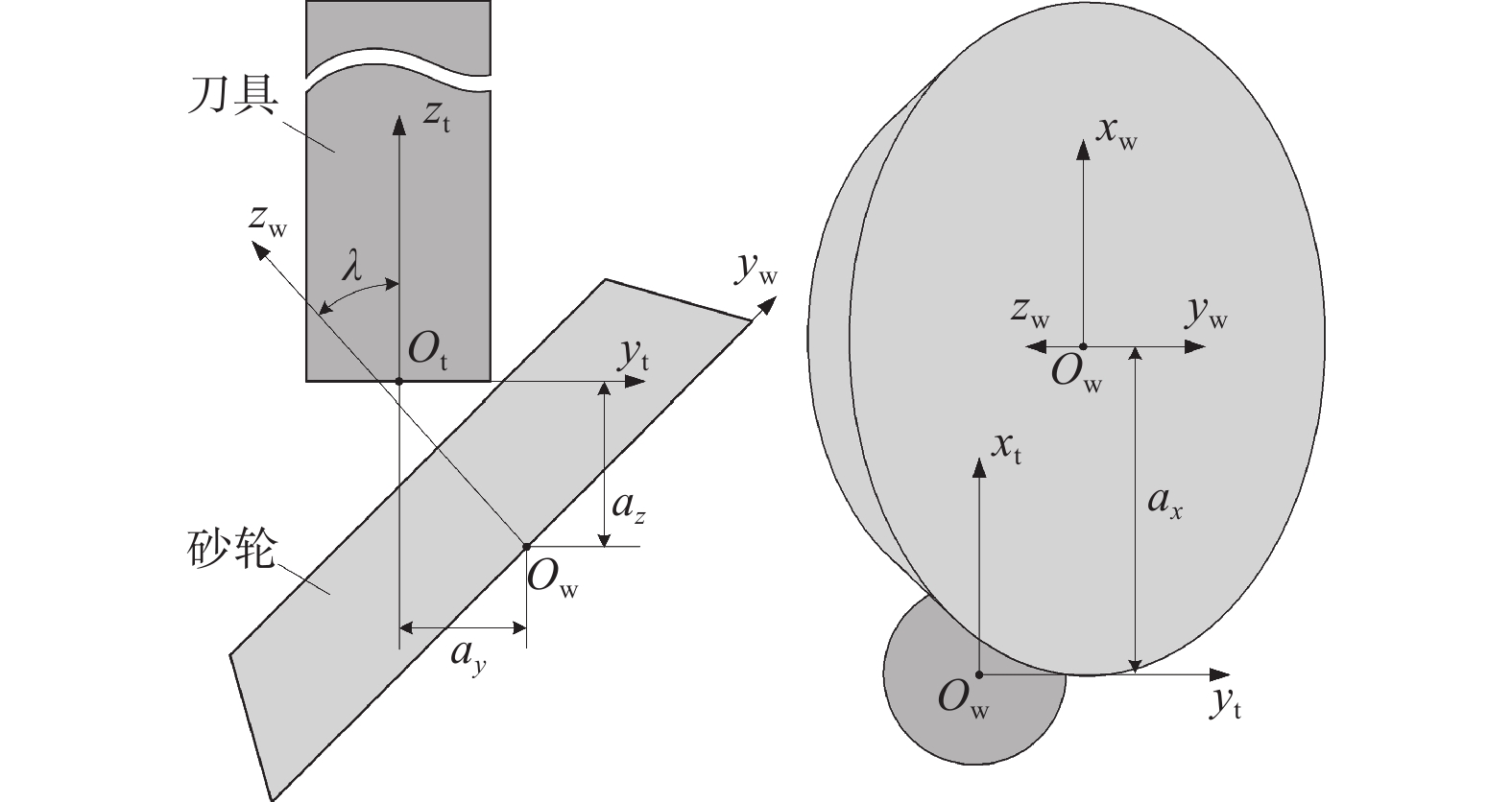
磨削容屑槽时,砂轮与刀具间的接触区几何形状复杂,为确定接触区形状,需要确定砂轮与容屑槽间的瞬时接触线。磨削开始前,砂轮相对刀具的初始位置如图1所示,其中:坐标系Sw(xw, yw, zw)与砂轮固连,xw和yw轴位于砂轮侧平面上,zw轴与砂轮轴线重合;坐标系St(xt, yt, zt)与刀具固连,xt和yt轴位于刀具端面上,zt轴与刀具轴线重合;az为砂轮与刀具的初始距离,ax、ay、λ为砂轮的安装位姿,决定了容屑槽的几何形状。在初始位置时,坐标系Sw到坐标系St的齐次坐标变换矩阵为:
$$ {{{\boldsymbol{M}}}_{{\text{tw}}}} = \left[ {\begin{array}{*{20}{c}} 1&0&0&{{a_x}} \\ 0&{\cos \lambda }&{ - \sin \lambda }&{{a_y}} \\ 0&{\sin \lambda }&{\cos \lambda }&{{a_{\textit{z}}}} \\ 0&0&0&1 \end{array}} \right] $$ (1)  图 2 砂轮回转面的几何定义Figure 2. Geometric definition of surface of revolution of grinding wheel
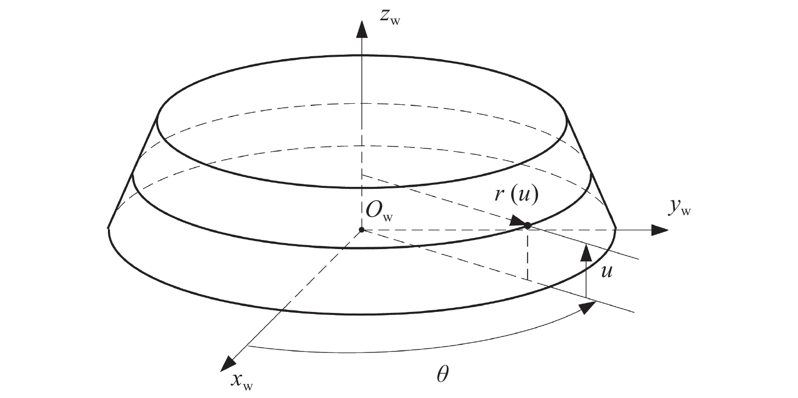
$$ {{\boldsymbol{r}}_{\text{w}}}(u,\theta ) = {[\begin{array}{*{20}{c}} {r(u)\cos \theta }&{r(u)\sin \theta }&u&1 \end{array}]^{\text{T}}} $$ (2) $$ {{{\boldsymbol{n}}}_{\text{w}}}(u,\theta ) = {[\begin{array}{*{20}{c}} {\cos \theta }&{\sin \theta }&{n(u)}&0 \end{array}]^{\text{T}}}/\sqrt {1 + {n^2}(u)} $$ (3) 其中:r(u)表示砂轮在宽度方向逐渐变化的半径;$ n(u) = - {\mathrm{d}}r(u)/{\mathrm{d}}u $。
磨削刀具容屑槽时,刀具视为静止,砂轮绕刀具轴线旋转并沿刀具轴线做直线进给。为生成容屑槽的螺旋曲面,砂轮绕刀具旋转的角速度ω与沿刀具轴线进给的进给速度va间需满足:
$$ \omega = {v_{\text{a}}}/({r_{\text{t}}}\cot \beta ) $$ (4) 其中:rt为刀具半径,β为刀具螺旋角。
磨削开始后,经过时间t,砂轮回转面上的点及其法向量在刀具坐标系中的坐标分别表示为:
$$ \begin{gathered} {{\boldsymbol{r}}_{\text{t}}}(u,\theta ,t) = \left[ {\begin{array}{*{20}{c}} {\cos \omega t}&{ - \sin \omega t}&0&0 \\ {\sin \omega t}&{\cos \omega t}&0&0 \\ 0&0&1&{{v_{\text{a}}}t} \\ 0&0&0&1 \end{array}} \right]{{\boldsymbol{M}}_{{\text{tw}}}}{{\boldsymbol{r}}_{\text{w}}} \\ \qquad\quad\;\; = \left[ {\begin{array}{*{20}{c}} {{x_{\text{t}}}(u,\theta ,t)} \\ {{y_{\text{t}}}(u,\theta ,t)} \\ {{{\textit{z}}_{\text{t}}}(u,\theta ,t)} \\ 1 \end{array}} \right] \\ \end{gathered} $$ (5) $$ {{\boldsymbol{n}}_{\text{t}}}(u,\theta ,t) = \left[ {\begin{array}{*{20}{c}} {\cos \omega t}&{ - \sin \omega t}&0&0 \\ {\sin \omega t}&{\cos \omega t}&0&0 \\ 0&0&1&{{v_{\text{a}}}t} \\ 0&0&0&1 \end{array}} \right]{{\boldsymbol{M}}_{{\text{tw}}}}{{\boldsymbol{n}}_{\text{w}}} $$ (6) 在砂轮回转面上,该点相对刀具的运动速度为:
$$ {{\boldsymbol{v}}_{\text{t}}} = \frac{{{\text{d}}{{\boldsymbol{r}}_{\text{t}}}}}{{{\text{d}}t}} $$ (7) 根据共轭曲面理论,砂轮曲面与容屑槽曲面在接触点处的相对速度与法向量需满足vt·nt=0,由此可得[14]:
$$ \theta \left( u \right) = \text{π} - {\sin ^{ - 1}}({c_3}/\sqrt {c_1^2 + c_2^2} ) - {\tan ^{ - 1}}({c_1}/{c_2}) $$ (8) 其中:
$$ \left\{ {\begin{array}{l} {{c_1} = - {a_y} - \left( {r(u)n(u) - u} \right)\sin \lambda } \\ {{c_2} = {a_x}\cos \lambda + r(u)\cot \beta \sin \lambda } \\ {{c_3} = {a_x}n(u)\sin \lambda - r(u)n(u)\cot \beta \cos \lambda } \end{array}} \right. $$ 在给定时间t,将砂轮离散为一组等厚度(厚度为Δu)的砂轮薄片,即令u=0, Δu, 2Δu,···, nΔu,再依次代入式(8)计算得到相应的θ值;将u和θ的值代入式(5)可得到砂轮与容屑槽的瞬时接触线上离散点的坐标。排除位于刀具圆柱体外的点即可得到砂轮与容屑槽的瞬时接触线,如图3所示。将图3的接触线上的各点按参数u的值由小到大进行排序,第i个点用Ci表示。
 图 3 砂轮与容屑槽的瞬时接触线Figure 3. Instantaneous contact line between grinding wheel and flute
1.2 当量磨削层厚度的计算
磨削容屑槽时砂轮表面各处的接触弧长逐渐变化,形成了如图3所示的不规则接触区。若用接触点Ci所在的砂轮薄片将刀具工件剖开,可得到如图4所示的砂轮与刀具的接触弧,由图4可见砂轮与工件间的接触关系与外圆磨削有很大不同。在外圆磨削时,接触弧长l与磨削深度a之间满足[15]:
$$ l = {(a{d_{\mathrm{e}}})^{1/2}} $$ (9) 其中:de为当量砂轮直径。
显然,式(9)并不适用于图4中的接触关系。为此,引入容屑槽磨削的当量磨削深度。假设接触点Ci所对应的接触弧长li与当量磨削深度ai之间满足:
$$ {a_i} = {c_4}l_i^2 $$ (10) 其中,系数c4的值与接触区形状有关。
由于工件进给速度比砂轮线速度小得多,接触弧长li可近似视为$\overset{\frown}{{{C}_{i}}C_{i}^{\prime}}$的弧长,点C'i为接触点Ci所在砂轮薄片与刀具回转面的交点。$\overset{\frown}{{{C}_{i}}C_{i}^{\prime}} $的弧长可由下式得到:
$$ {l_i} = ({\theta _i} - {\theta '_i})r({u_i}) $$ (11) 其中:ui和θi为接触点Ci对应的参数值,θ'i为切入点C'i对应的参数值。θ'i可通过下式求解得到:
$$ x_{\text{t}}^2\left( {{u_i},{{\theta '}_i},t} \right) + y_{\text{t}}^2\left( {{u_i},{{\theta '}_i},t} \right) = r_{\text{t}}^2{\text{ }}\left(\frac{\text{π} }{2} < {\theta '_i} < {\theta _i}\right) $$ (12) 为计算当量磨削层厚度,还需要得到刀具工件的进给速度vw。由于磨削深度较大而刀具半径较小,Ci和C'i处的工件进给速度差异较大,因此将Ci和C'i中间点Mi处的工件进给速度视为刀具工件的进给速度。中间点Mi到刀具轴线的距离为:
$$ {r_{Mi}} = ({r_{Ci}} + {r_{\text{t}}})/2 $$ (13) 其中rCi为接触点Ci到刀具轴线的距离,由下式得到:
$$ {r_{Ci}} = \sqrt {x_{\text{t}}^{\text{2}}({u_i},{\theta _i},t) + y_{\text{t}}^2({u_i},{\theta _i},t)} $$ (14) 若视砂轮静止、工件运动,结合式(4)可得Mi点的圆周速度vp为:
$$ {v_{\text{p}}} = {v_{\text{a}}}{r_{Mi}}/({r_{\text{t}}}\cot \beta ) $$ (15) 式中vp的方向与直线进给速度va的方向垂直,由此可得Mi点的合速度vr为:
$$ {v_{\text{r}}} = {(v_{\text{p}}^2 + v_{\text{a}}^2)^{1/2}} $$ (16) 由于vr不在砂轮薄片所在平面,而且砂轮与刀具的接触关系复杂,vr不能等同于刀具工件的进给速度,因此引入工件的当量进给速度vw:
$$ {v_{\text{w}}} = {c_5}{v_{\text{r}}} $$ (17) 其中,系数c5的值与接触区形状有关。
根据当量磨削层厚度的定义[15],接触点Ci所在砂轮薄片的当量磨削层厚度为:
$$ {h_{{\text{eq}},i}} = \frac{{{v_{\text{w}}} \cdot {a_i}}}{{{v_{{\text{s}},i}}}} = \frac{{{c_4}{c_5}{v_{\mathrm{r}}}l_i^2}}{{{v_{{\text{s}},i}}}} $$ (18) 其中,vs,i为接触点Ci所在砂轮薄片的线速度。
由于系数c4和c5均与接触区形状有关,引入磨削接触区形状系数α=c4c5,则有:
$$ {h_{{\text{eq}},i}} = \frac{{\alpha {v_{\mathrm{r}}}l_i^2}}{{{v_{{\text{s}},i}}}} $$ (19) 为计算当量磨削层厚度,需要确定系数α的值。
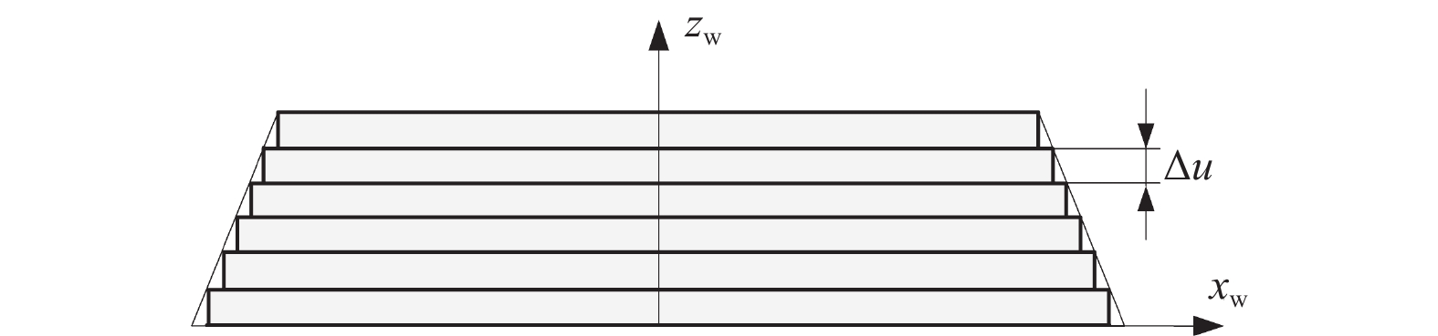
本研究将砂轮离散为一组等厚度的砂轮薄片,砂轮薄片的厚度为Δu,如图5所示。接触点Ci所在砂轮薄片的局部材料去除率为:
$$ {Q_i} = \Delta u{a_i}{v_{\text{w}}} = \alpha \Delta u{v_{\text{r}}}l_i^2 $$ (20) 考虑所有参与磨削的砂轮薄片,其总的材料去除率为:
$$ Q = \sum {{Q_i}} = \alpha \Delta u{v_{\text{r}}}\sum {l_i^2} $$ (21) 对于普通圆柱形整体刀具,容屑槽的横截面形状恒定,因此磨削容屑槽时总的材料去除率也可表示为:
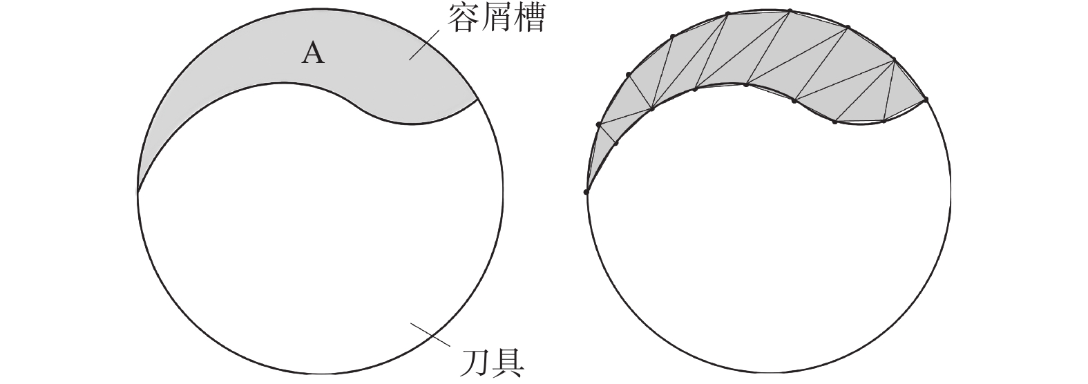
$$ Q = A{v_{\text{a}}} $$ (22) 其中,A为容屑槽横截面廓形的面积。
图6为容屑槽的横截面廓形。如图6所示:可将容屑槽横截面廓形离散化为一个个小三角形,所有三角形面积之和即为容屑槽横截面廓形的面积A。联立式(21)和式(22)可得:
$$ \alpha = A{v_{\text{a}}}/(\Delta u{v_{\text{r}}}\sum {l_i^2} ) $$ (23) 将式(23)代入式(19),即可求得各砂轮薄片的当量磨削层厚度。
1.3 容屑槽磨削功率计算
根据磨削功率与当量磨削层厚度之间的数学关系[16],接触点Ci所在砂轮薄片消耗的局部磨削功率为:
$$ {P_i} = \Delta uK \cdot h_{{\text{eq}},i}^f $$ (24) 将所有参与磨削的砂轮薄片消耗的局部磨削功率相加得到总磨削功率:
$$ P = \sum {{P_i}} = \Delta uK\sum {h_{{\text{eq}},i}^f} $$ (25) 其中:K和f与砂轮形貌、工件材料、磨削液等因素有关,通过磨削实验来确定K和f的值。
2. 实验验证
2.1 实验条件
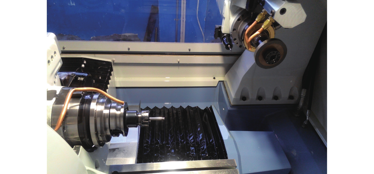
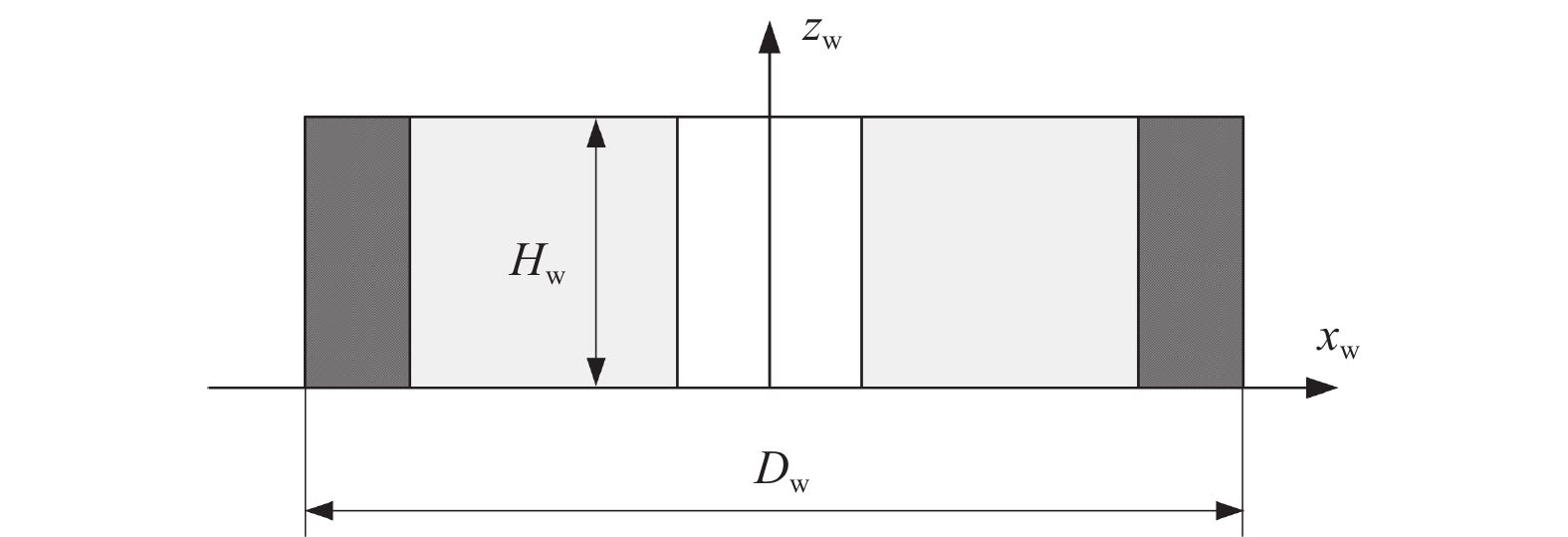
为验证上述功率模型的正确性,在ANCA MX7五轴数控工具磨床上进行容屑槽磨削实验,五轴数控工具磨床如图7所示。实验采用1A1金属结合剂金刚石砂轮,其金刚石磨料粒度代号为230/270,砂轮宽度Hw = 9.973 mm,初始砂轮直径Dw = 99.868 mm,砂轮几何形状如图8所示。磨削的工件是直径为7.94 mm的圆柱硬质合金精磨棒料,材料牌号为YG6X。采用顺磨工艺,容屑槽一次走刀完成。为保证每次磨削时砂轮表面的磨粒状态一致,在每次磨削前执行机床自带的砂轮修整程序,使用绿碳化硅砂轮(其规格为80 × 25 × 32-GC60K)对金刚石砂轮进行修整,修整后测量新的砂轮直径。实验通过机床配套磨削软件iGrind的数据记录功能记录机床PLC的主轴功率数据。
2.2 实验参数
实验中磨制的容屑槽的参数如表1所示,磨制该容屑槽所需要的砂轮安装位姿为:ax = 51.535 mm,ay = −5.097 mm,λ = 43.768°。砂轮安装位姿由文献[17]提供的方法计算得到。为了减小工件受力产生的弯曲变形,在保证磨削过程中砂轮与刀柄不发生碰撞的前提下,工件的伸出长度要尽可能短,实验中工件的伸出长度为50 mm。共进行20组实验,为减小随机误差的影响,每组实验磨削2次,将2次磨削功率数据取均值。
表 1 容屑槽几何参数Table 1. Geometric parameters of flute容屑槽几何参数 数值 螺旋角 β / (°) 30 径向前角 γ / (°) 5 芯径 dc / mm 4 槽宽 φ / (°) 150 磨削加工实验参数如表2所示,其中的砂轮线速度的调整范围为18~24 m/s,工件轴向进给速度的调整范围为60~90 mm/min,偏置Δax的调整范围为0~1.2 mm。偏置Δax用于改变容屑槽的深度,正偏置使深度减小。表2中的1~4号实验组为2因素2水平实验,只考虑砂轮线速度vs和工件轴向进给速度va的影响,用于确定功率模型中系数K和f的值;5~20号实验组为3因素4水平实验,用于对功率模型进行验证。
表 2 磨削加工实验参数Table 2. Grinding parameters in experiments实验组编号 砂轮线速度
vs / (m·s−1)工件轴向进给速度
va / (mm·min−1)偏置
Δax / mm1 18 60 0 2 18 90 0 3 24 60 0 4 24 90 0 5 18 70 1.2 6 22 90 0 7 20 90 1.2 8 24 70 0 9 18 80 0 10 22 60 1.2 11 20 60 0 12 24 80 1.2 13 18 60 0.8 14 22 80 0.4 15 20 80 0.8 16 24 60 0.4 17 18 90 0.4 18 22 70 0.8 19 20 70 0.4 20 24 90 0.8 2.3 实验结果与讨论
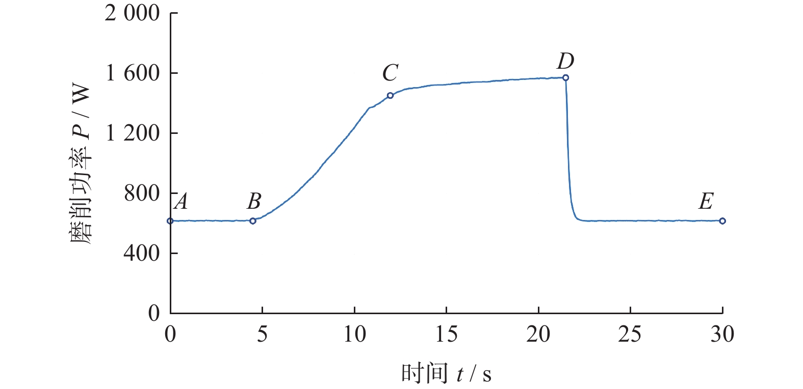
在磨削容屑槽的过程中,砂轮与工件的接触区域以及砂轮表面的磨粒状态是动态变化的,因此磨削功率也是逐渐变化的。以9号实验组为例,机床记录的功率变化曲线如图9所示,可明显看出功率曲线的变化分为4个阶段:
(1)在AB阶段,砂轮逐渐靠近工件,但尚未与工件接触,此时主轴消耗的功率为空转功率PA;
(2)在BC阶段,砂轮与工件发生接触,而且接触区域逐渐变大,此时主轴消耗的功率快速上升;
(3)在CD阶段,砂轮与工件保持稳定接触,接触区域形状恒定不变,此时主轴消耗的功率缓慢上升,主要是由于此时的切削深度大、磨削力大,砂轮表面磨粒被逐渐磨钝;
(4)在DE阶段,砂轮与工件脱开,主轴消耗的功率迅速下降为空转功率。
本文所指的磨削功率是砂轮与工件稳定接触时用于去除工件材料所消耗的功率,因此在处理磨削功率数据时,应该用CD段消耗的功率减去AB段的空转功率。另外,为了减小砂轮磨损对系数K和f的影响,令磨削功率P = PC − PA,其中PC为主轴在C点所消耗的总功率。
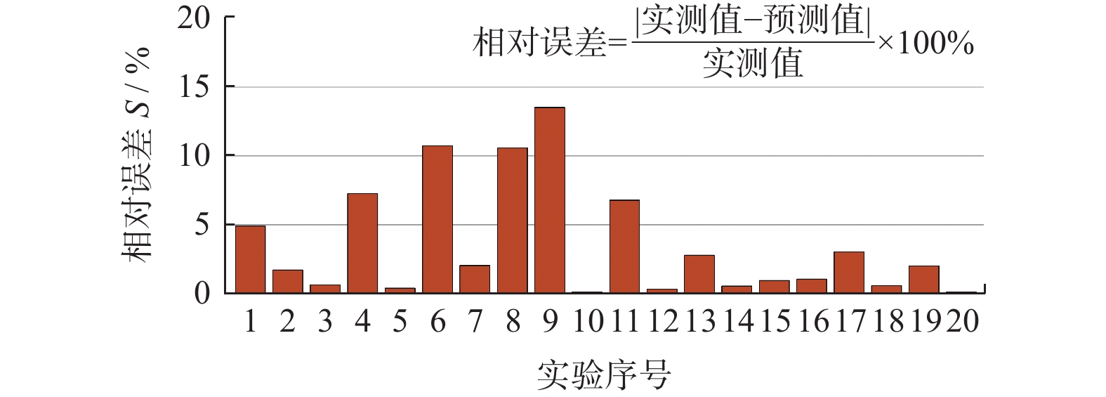
将1~4号实验组测得的磨削功率代入式(25)得到4个方程,其中的heq,i由1.2小节提出的方法确定,此时4个方程仅包含2个未知数(K和f),构成一组超定方程组。使用MATLAB中的fsolve函数求解该方程组,得到K = 8.994 × 10⁴、f = 0.735。将K和f的值代入磨削功率模型即可对表2中各实验组的磨削功率进行预测。各组实验的实测和预测磨削功率如图10所示,预测磨削功率的相对误差如图11所示。由图11可见:预测磨削功率与实测磨削功率接近,预测磨削功率的最大相对误差 < 15.0%,验证了功率模型的正确性。
 图 10 各组实验的实测与预测磨削功率Figure 10. Measured and predicted grinding power in each experiment
 图 11 各组实验预测磨削功率的相对误差Figure 11. Relative error of predicted grinding power in each experiment
另外,由1.2小节的分析和推导可知:砂轮在宽度方向上的当量磨削层厚度是不同的,因此在砂轮宽度方向上各砂轮薄片所消耗的磨削功率也不相同。图12为9号实验组中计算得到的砂轮宽度方向上不同位置的当量磨削层厚度和单位宽度磨削功率。从图12可见:最大当量磨削层厚度和最大单位宽度磨削功率存在于砂轮边缘处,因而砂轮边缘承受最大的磨削力和磨削热。由此可以推断砂轮边缘是砂轮磨损最严重的位置,该结论与LIU 等[18]的实验结果以及UHLMANN等[10]的仿真结果一致。
 图 12 砂轮宽度方向上的当量磨削层厚度和单位宽度磨削功率Figure 12. Equivalent chip thickness and grinding power per unit width along grinding wheel width
3. 结论
针对整体刀具容屑槽磨削,将砂轮离散为一组等厚度的砂轮薄片,通过引入磨削接触区形状系数,提出各砂轮薄片当量磨削层厚度的计算方法,并基于当量磨削层厚度建立整体刀具容屑槽磨削的磨削功率模型,得出如下结论。
(1)磨削实验结果表明:容屑槽磨削功率的预测值与测量值之间的最大相对误差 < 15.0%,验证了功率模型的正确性。
(2)仿真结果表明:沿砂轮宽度方向上的当量磨削层厚度以及单位宽度磨削功率是逐渐变化的,其最大当量磨削层厚度和最大单位宽度磨削功率存在于砂轮边缘处,沿砂轮宽度方向上逐渐变化的当量磨削层厚度将会导致砂轮宽度方向上的非均匀磨损。
-

图 2 砂轮回转面的几何定义
Figure 2. Geometric definition of surface of revolution of grinding wheel
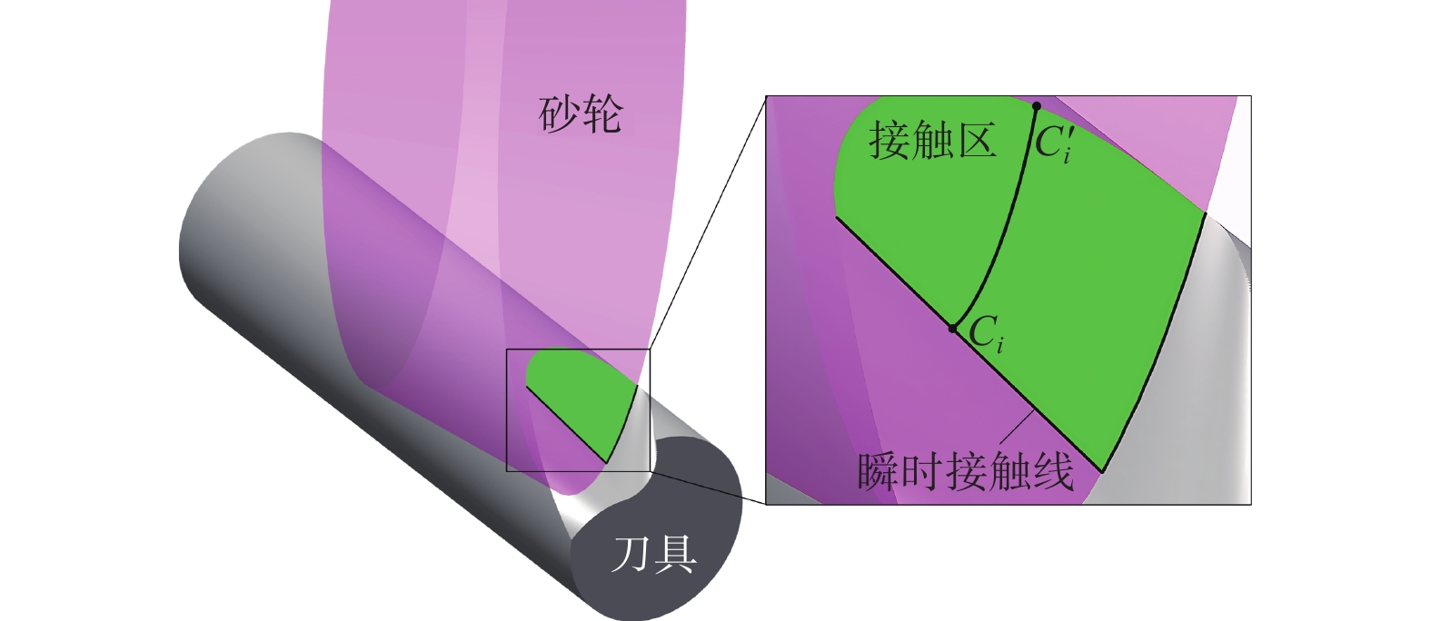
图 3 砂轮与容屑槽的瞬时接触线
Figure 3. Instantaneous contact line between grinding wheel and flute
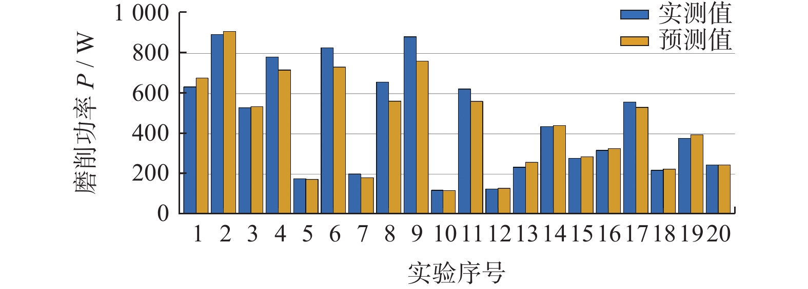
图 10 各组实验的实测与预测磨削功率
Figure 10. Measured and predicted grinding power in each experiment

图 11 各组实验预测磨削功率的相对误差
Figure 11. Relative error of predicted grinding power in each experiment
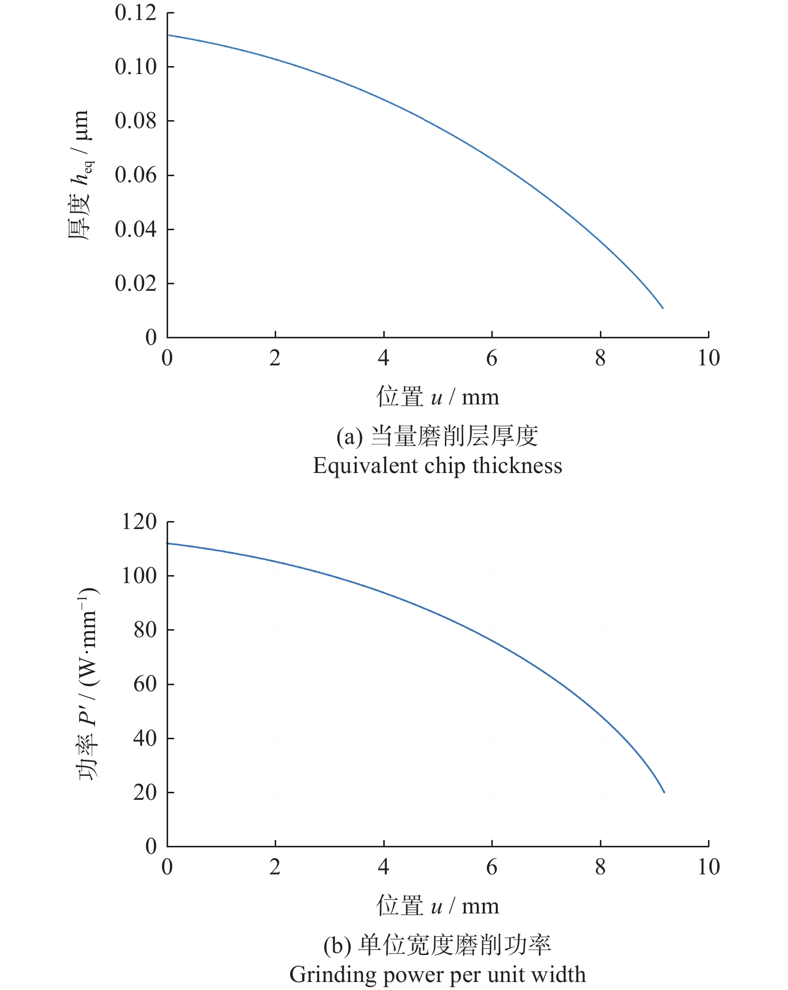
图 12 砂轮宽度方向上的当量磨削层厚度和单位宽度磨削功率
Figure 12. Equivalent chip thickness and grinding power per unit width along grinding wheel width
表 1 容屑槽几何参数
Table 1. Geometric parameters of flute
容屑槽几何参数 数值 螺旋角 β / (°) 30 径向前角 γ / (°) 5 芯径 dc / mm 4 槽宽 φ / (°) 150  下载: 导出CSV
表 2 磨削加工实验参数
Table 2. Grinding parameters in experiments
实验组编号 砂轮线速度
vs / (m·s−1)工件轴向进给速度
va / (mm·min−1)偏置
Δax / mm1 18 60 0 2 18 90 0 3 24 60 0 4 24 90 0 5 18 70 1.2 6 22 90 0 7 20 90 1.2 8 24 70 0 9 18 80 0 10 22 60 1.2 11 20 60 0 12 24 80 1.2 13 18 60 0.8 14 22 80 0.4 15 20 80 0.8 16 24 60 0.4 17 18 90 0.4 18 22 70 0.8 19 20 70 0.4 20 24 90 0.8
下载: 导出CSV
-
[1] 宋铁军, 周志雄, 李伟, 等. 硬质合金立铣刀螺旋槽磨削表面粗糙度模型研究 [J]. 机械工程学报,2017,53(17):185-192. doi: 10.3901/JME.2017.17.185SONG Tiejun, ZHOU Zhixiong, LI Wei, et al. Roughness model for helical flute of cemented carbide end mill under grinding [J]. China Mechanical Engineering,2017,53(17):185-192. doi: 10.3901/JME.2017.17.185 [2] 毕雪峰, 杨承三, 景璐璐. 深切缓进给磨削烧伤实验研究 [J]. 上海理工大学学报,2014,36(3):303-306. doi: 10.13255/j.cnki.jusst.2014.03.018BI Xuefeng, YANG Chengsan, JING Lulu. Experimental research on grinding burn in creep feed grinding [J]. Journal of University of Shanghai for Science and Technology,2014,36(3):303-306. doi: 10.13255/j.cnki.jusst.2014.03.018 [3] MENG Q Y, GUO B, ZHAO Q L, et al. Modelling of grinding mechanics: A review [J]. Chinese Journal of Aeronautics,2023,36(7):25-39. doi: 10.1016/j.cja.2022.10.006 [4] 宋铁军, 周志雄, 李伟, 等. 硬质合金刀具螺旋槽缓进给磨削力研究 [J]. 中国机械工程,2014,25(9):1153-1158. doi: 10.3969/j.issn.1004-132X.2014.09.004SONG Tiejun, ZHOU Zhixiong, LI Wei, et al. Research on grinding forces of creep feed grinding cemented carbide tool helical grooves [J]. China Mechanical Engineering,2014,25(9):1153-1158. doi: 10.3969/j.issn.1004-132X.2014.09.004 [5] 赵延军, 钱灌文, 刘权威, 等. 砂轮刚性对磨削性能及产品加工质量的影响 [J]. 金刚石与磨料磨具工程,2017,37(1):56-60. doi: 10.13394/j.cnki.jgszz.2017.1.0011ZHAO Yanjun, QIAN Guanwen, LIU Quanwei, et al. Influence of wheel stiffness on grinding performance and product machining quality [J]. Diamond & Abrasives Engineering,2017,37(1):56-60. doi: 10.13394/j.cnki.jgszz.2017.1.0011 [6] SALATA M. The analysis of the influence of technological parameters on the grinding temperature in the single-pass grinding process of solid carbide end mill flutes [J]. Advances in Science and Technology-Research Journal,2022,16(1):190-202. doi: 10.12913/22998624/143483 [7] DE PAYREBRUNE K M, KRÖGER M. Dynamical aspects in modeling long cantilevering workpieces in tool grinding [J]. Journal of Sound and Vibration,2015,355:407-417. doi: 10.1016/j.jsv.2015.06.027 [8] DE PAYREBRUNE K M, KRÖGER M. An integrated model of tool grinding: challenges, chances and limits of predicting process dynamics [J]. Production Engineering,2016,10:421-432. doi: 10.1007/s11740-016-0687-2 [9] DENKENA B, DITTRICH M A, BÖß V, et al. Self-optimizing process planning for helical flute grinding [J]. Production Engineering,2019,13:599-606. doi: 10.1007/s11740-019-00908-0 [10] UHLMANN E, GÜLZOW B, MUTHULINGAM A. Optimising the grinding wheel design for flute grinding processes utilising numerical analysis of the complex contact conditions [J]. Journal of Machine Engineering,2020,20(3):85-94. doi: 10.36897/jme/119641 [11] DITTRICH M A, BÖß V, WICHMANN M, et al. Simulation-based compensation of deflection errors in helical flute grinding [J]. CIRP Journal of Manufacturing Science and Technology,2020,28:136-143. doi: 10.1016/j.cirpj.2019.11.002 [12] JEYARAJ D, LAHMANN H W, WELZEL F. A data-driven model to predict dressing interval during a multi-flute end mill grooving process using a multilayered diamond grinding wheel [J]. Procedia CIRP,2023,117:353-358. doi: 10.1016/j.procir.2023.03.060 [13] WIESENER F, BERGMANN B, WICHMANN M, et al. Modeling of heat transfer in tool grinding for multiscale simulations [J]. Procedia CIRP,2023,117:269-274. doi: 10.1016/j.procir.2023.03.046 [14] REN L, XU J, ZHANG XM, et al. Determination of wheel position in flute grinding of cylindrical end-mills considering tolerances of flute parameters [J]. Journal of Manufacturing Processes,2022,74:63-74. doi: 10.1016/j.jmapro.2021.11.065 [15] MALKIN S, GUO CS. Grinding technology: Theory and application of machining with abrasives [M]. New York: Industrial Press, 2008. [16] CHEN X, ROWE W B, ALLANSON D R, et al. A grinding power model for selection of dressing and grinding conditions [J]. Journal of Manufacturing Science and Engineering,1999,121(4):632-637. doi: 10.1115/1.2833084 [17] 任磊, 韩家祥, 张新民, 等. 圆弧投影法在圆柱立铣刀容屑槽刃磨中的应用 [J]. 机械工程学报,2023,59(17):335-348. doi: 10.3901/JME.2023.17.335REN Lei, HAN Jiaxiang, ZHANG Xinmin, et al. Application of circular arc projection method in flute grinding of cylindrical end-mills [J]. Journal of Mechanical Engineering,2023,59(17):335-348. doi: 10.3901/JME.2023.17.335 [18] LIU X L, CHEN Z, JI W, et al. A compensation method for wheel wear in solid cutting tool groove grinding based on iteration algorithm [J]. The International Journal of Advanced Manufacturing Technology,2020,107:3389-3399. doi: 10.1007/s00170-020-05269-y -


 下载:
下载:


 点击查看大图
计量
- 文章访问数: 56
- HTML全文浏览量: 28
- PDF下载量: 3
- 被引次数: 0
 邮件订阅
邮件订阅 RSS
RSS